How Venturi Fertigation Systems Control Fertilizer Injection
Venturi fertigation systems use a pressure differential to draw concentrated fertilizer solution into irrigation water without a separate injection pump. For technical evaluators, understanding this operating principle is essential to assessing injection stability, nutrient delivery, and system compatibility. Inlet and outlet pressures, water flow, injector sizing, and fertilizer solution properties all influence performance. The question is not simply whether an injector can draw fertilizer, but whether it can deliver the intended dose across the irrigation system’s actual operating range.
Where the suction comes from
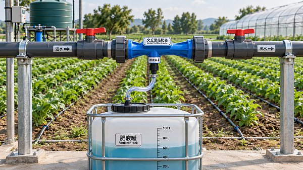
A Venturi injector narrows the water passage through a throat. As water accelerates through that restriction, static pressure at the throat falls. If the pressure there is low enough relative to the pressure acting on the fertilizer solution, liquid is drawn through a suction port and mixed with the water stream. The passage then widens, allowing some pressure to be recovered downstream.
The important distinction is between a pressure difference and a fixed injection rate. The injector has no inherent way to measure how much nutrient the crop needs. It responds to hydraulic conditions. A change in upstream pressure, downstream pressure, water flow, suction lift, or restriction in the fertilizer line can change the amount drawn in.
This is why an injector that performs well during commissioning may behave differently when another irrigation zone opens or a filter becomes dirty. It may still be drawing solution, but not at the rate used to calculate the fertilizer application.
Pressure loss is part of the design, not a fault
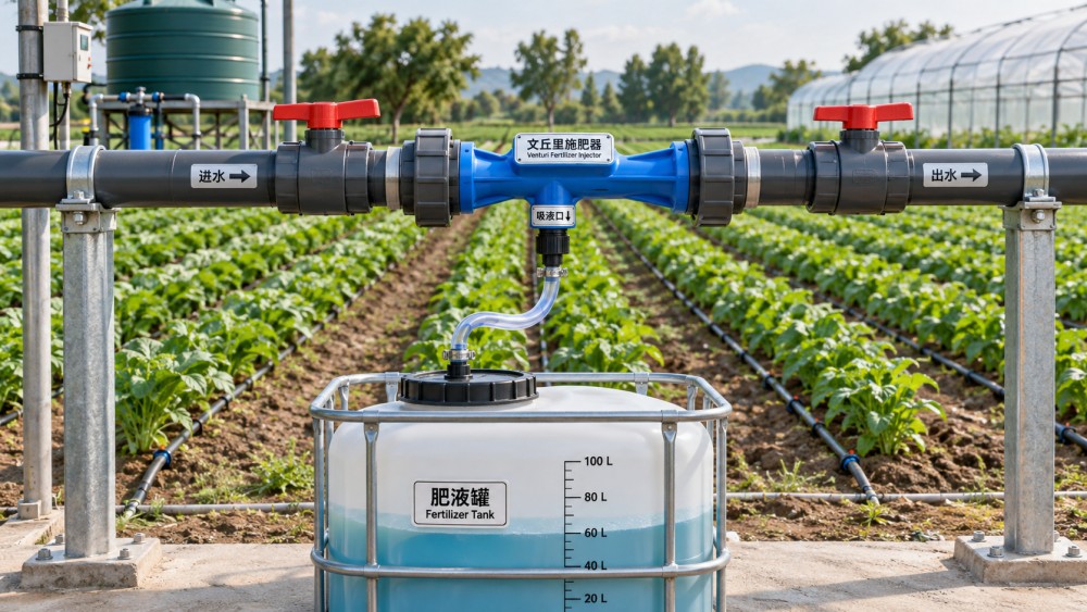
A Venturi needs energy from flowing water. In a direct inline installation, all or a substantial portion of the irrigation flow passes through the injector, so the pressure loss must be compatible with the downstream system. In a bypass arrangement, only part of the flow passes through the injector. A pressure difference between the bypass takeoff and return drives that flow; a control valve, an existing pressure difference, or a booster arrangement may provide it.
A bypass does not make the energy requirement disappear. Throttling a mainline valve to create the required differential can reduce pressure available to emitters. A booster pump can preserve more mainline pressure in some designs, but adds equipment and energy use. The right arrangement depends on the available pressure budget, the injector curve, and the pressure needed at the most hydraulically disadvantaged part of the field.
Check pressure at the injector inlet and outlet while the relevant zone is operating, not only at the pump. Pipe friction, elevation, filtration equipment, and other valves can make the pressure at the injector quite different from the pump discharge reading. If the available differential is marginal, a system may inject under one zone configuration and stop drawing under another.
Sizing requires more than matching pipe diameter
Connection size is not a reliable substitute for an injector performance curve. Two units with similar connections may have different throat geometries, water-flow requirements, pressure losses, and suction capacities. An oversized injector may not develop the conditions needed for consistent suction at low flow. An undersized unit may create excessive pressure loss or limit the volume of stock solution that can be injected during the available time.
Ask for manufacturer performance data covering inlet pressure, outlet pressure or differential, injector water flow, and suction flow. Confirm the test conditions behind the data, particularly the suction lift and the liquid used. A published suction rate measured with water should not automatically be treated as the rate for a denser or more viscous fertilizer concentrate.
Evaluate the injector against the full operating envelope: minimum and maximum irrigation flow, expected pressure variation, different zone combinations, and the required duration of fertilizer application. Include conditions near the end of a filter service interval, rather than assuming a clean system throughout. If the fertilizer tank will be below the injector, include the practical suction lift and the increasing lift as the tank empties.
A useful sizing check
Suppose an irrigation zone runs at 20 cubic meters per hour and the intended stock-solution injection rate is 20 liters per hour. The nominal dilution is approximately one part stock solution per 1,000 parts irrigation water, ignoring the small contribution of stock solution to total flow. This is an illustrative calculation, not an injector specification.
If irrigation flow falls to 15 cubic meters per hour while injection remains at 20 liters per hour, the delivered stock concentration rises. Conversely, a reduction in suction with unchanged irrigation flow lowers it. In a real Venturi installation both flows can change at once, so their ratio should be measured rather than inferred from either reading alone.
How injection rate is adjusted—and what limits control
Operators commonly adjust suction with a metering valve, regulate the pressure difference across the injector, or change stock concentration and injection time. A suction-side valve is useful for setting a rate, but it does not by itself compensate for fluctuations in irrigation flow or pressure. Likewise, a fixed valve position is not a permanent calibration.
For a batch application, the total amount removed from the tank matters as well as the instantaneous rate. If the tank empties early, plants receive plain irrigation water for the remainder of the cycle; if solution remains when the zone closes, the planned nutrient quantity has not been applied. A level scale or measured tank volume provides a practical check, while a suitable flowmeter can give more detailed information where justified.
Electrical conductivity monitoring can help identify changes in the mixed irrigation stream, especially when used with a baseline measurement of the source water. It is not a direct measurement of each nutrient. Different fertilizer salts contribute differently to conductivity, and source-water conductivity may vary. Use it as a process indicator, not as the sole proof that a formulation has delivered the intended nutrient balance.
Where close, repeatable proportional dosing is required across widely varying flows, compare the Venturi arrangement with a metering pump or a flow-proportional injection system. Those alternatives add components and maintenance, but they may offer a control capability that a manually adjusted injector cannot provide on its own.
Fertilizer chemistry can change hydraulic performance
A clear stock solution is usually easier to inject consistently than one carrying undissolved material. Particles can obstruct the suction strainer, metering valve, or injector passage; deposits downstream can also affect filters and emitters. Solubility depends on the fertilizer, concentration, water temperature, and other dissolved salts. A formulation that dissolves under preparation conditions may still crystallize if the tank cools or water evaporates.
Compatibility needs particular attention when concentrates are mixed. Calcium-containing products, for example, can form precipitates with phosphate or sulfate sources under unsuitable conditions. Separate stock tanks are often used to keep incompatible concentrates apart until sufficient dilution occurs, but separation alone is not a substitute for checking the supplier’s mixing instructions and the actual water chemistry.
Humic products, micronutrient blends, acids, and other specialty inputs deserve the same scrutiny. Check whether the product is intended for the planned irrigation method, whether agitation is needed, and whether the injector, seals, tubing, and tank materials are compatible. A small compatibility test using the actual source water and intended mixing sequence can expose an obvious problem before it reaches the field, although it cannot establish long-term stability by itself.
This connection between formulation and application is central to the fertilizer technology coverage of the Global Fine Chemicals & Agrochemical Intelligence Network (FCAS). For evaluators, a fertilizer’s nutrient analysis is only one part of the decision; solubility, handling, documentation, and compatibility with the injection equipment also affect whether the stated nutrients reach the crop as intended.
Commissioning: measure the ratio under real conditions
A practical commissioning test starts with clean water in the stock tank and the irrigation zone operating at its normal setting. Record injector inlet and outlet pressures, irrigation flow, suction-line configuration, and the volume drawn over a measured period. Repeat at relevant low- and high-flow conditions and with other zone combinations that could affect pressure.
Then check the result with the intended fertilizer solution, using appropriate handling precautions. Compare the measured suction rate with the water test and observe whether it changes as the tank level falls. If the product requires agitation, test with agitation operating as intended. Document the valve settings, but also document the pressures and flows associated with those settings; a valve position without operating conditions is difficult to reproduce.
Allow time for the mixed solution to travel from the injection point through the irrigation network. A short injection period can produce uneven timing between near and distant emitters, particularly in long or branched systems. Sampling at representative points can help establish when fertilizer arrives and when the line has returned to the source-water baseline. Plan a clean-water flush appropriate to the system and fertilizer after injection.
Backflow protection and operating boundaries
Fertilizer must not be allowed to contaminate the water source if flow stops or pressure reverses. The required backflow prevention arrangement depends on the water source, connected equipment, local rules, and the authority responsible for the installation. A suction-line check valve may prevent some reverse movement in that line, but it should not be assumed to replace the backflow protection required for the irrigation supply.
Consider shutdown as well as normal operation: what happens if the pump stops, a zone valve closes, the stock tank empties, or a suction tube leaks air? Isolation valves, appropriate interlocks, accessible cleaning points, and a safe method for flushing or draining the injector make faults easier to manage. Operators also need the fertilizer supplier’s handling and emergency information, particularly for corrosive concentrates.
Before approving a design, request the injector curves, a pressure-loss assessment, material compatibility information, and a commissioning method tied to the actual irrigation zones. If the required dose is acceptable only at one ideal pressure point, the design needs more work. A sound Venturi selection is one that continues to draw and mix predictably when the system operates as a farm or facility actually runs it.
Facing technical bottlenecks in manufacturing or looking for more efficient industrial solutions? Leave your details below and let the engineering experts at FCAS solve them for you.
We respect your privacy. Your information is strictly confidential.
Related News
 Micelle Fluidics & ChelationHow High Performance Industrial Dispersants Prevent SettlingHigh performance industrial dispersants can limit settling and improve redispersibility. Discover how to select and test the right chemistry for your formulation.MORE+
 Micelle Fluidics & ChelationHow to Choose a Detergent Builders ManufacturerChoose a detergent builders manufacturer with confidence. Compare quality, formulation fit, total costs, and supply reliability before you buy.MORE+
 Micelle Fluidics & ChelationHow Venturi Fertigation Systems Control Fertilizer InjectionDiscover how venturi fertigation systems control fertilizer injection, and learn how pressure, sizing, and calibration affect dosing accuracy.MORE+
 Micelle Fluidics & ChelationHow to Use Cocamidopropyl Betaine for Hand Soap FormulasDiscover how to use cocamidopropyl betaine for hand soap, balance surfactants, adjust pH and viscosity, and troubleshoot common formulation issues.MORE+
 Micelle Fluidics & ChelationHow to Evaluate an Industrial Dispersants ManufacturerEvaluate an industrial dispersants manufacturer with confidence. Learn how to assess formulation performance, batch consistency, quality controls and supply risk.MORE+
 Micelle Fluidics & ChelationHow Cationic Surfactants Affect Emulsion StabilityCationic Surfactants can improve emulsion stability—but formulation matters. Discover key risks, compatibility checks, and practical troubleshooting tips.MORE+
 Micelle Fluidics & ChelationHow Eco Friendly Detergent Builders Perform in Hard WaterExplore how eco friendly detergent builders tackle hard water, compare citrate, zeolite and chelants, and find the right approach for cleaner results.MORE+
 Micelle Fluidics & ChelationHow Does Cocamidopropyl Betaine Affect Foam and Skin Mildness?Discover how Cocamidopropyl Betaine can enhance foam and support skin mildness. Explore formulation tips, impurity controls, and testing strategies for better cleansers.MORE+
 Micelle Fluidics & ChelationWhich Detergent Builders for Hard Water Prevent Mineral Buildup?Compare detergent builders for hard water, including MGDA, GLDA, citrate and zeolites. Discover how to prevent mineral buildup, reduce residue and choose the right formulation.MORE+
 Micelle Fluidics & ChelationHow Anionic Industrial Dispersants Improve Coating StabilityAnionic industrial dispersants improve coating stability, pigment wetting, viscosity control, gloss, and storage performance. Learn how to select and test the right solution.MORE+
 Micelle Fluidics & ChelationWhat Are Cationic Surfactants and Where Are They Commonly Used?Cationic Surfactants deliver powerful surface affinity for disinfection, fabric softening, hair conditioning, antistatic control, and industrial treatments. Explore key uses and selection factors.MORE+
 Micelle Fluidics & ChelationHow Cationic Surfactants Improve Formulation Performance and StabilityCationic Surfactants improve deposition, conditioning, anti-static control, and formulation stability. Explore compatibility, dispersion, and selection insights for better-performing products.MORE+
 Micelle Fluidics & ChelationIndustrial Dispersants for Pigments and Fillers: How to Improve Stability and FlowIndustrial Dispersants help improve pigment and filler stability, boost flow, and reduce defects in production. Discover how the right choice can cut rework and improve results.MORE+